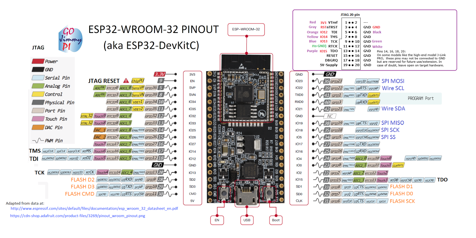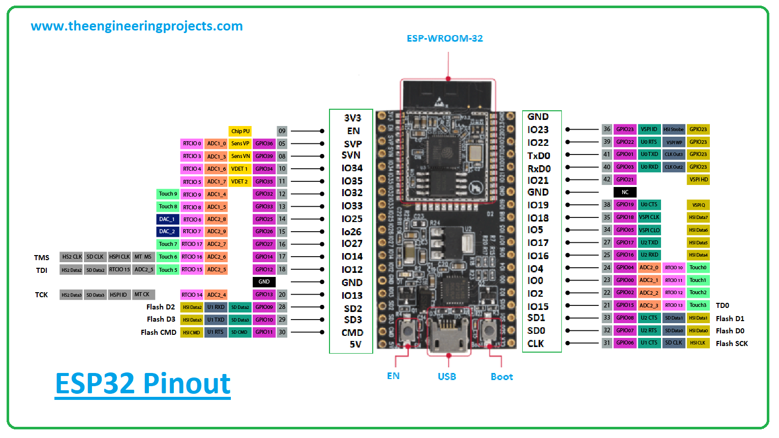

You should not use that pin to power the board. There is also the pin VCC (yellow color). However, a lot of people recommend powering the board through the 5V pin. The board can be powered through the 3.3V or 5V pins. There are three GND pins (black color) and two power pins (red color): 3.3V and 5V. It is internally connected to a 10k Ohm pull-up resistor. When GPIO 0 is connected to GND, the ESP32 is in flashing mode. GPIO 0 determines whether the ESP32 is in flashing mode or not. But remember, if you occupy them, you would not be able to open the Serial Monitor. You can use GPIO 1 and GPIO 3 to connect other peripherals. Because the board does not have a built-in programmer, you need to use these pins to communicate with an FTDI programmer and upload the code. GPIO 1 (TX) and GPIO 3 (RX) are serial pins. You can follow the figure 2 as we progress. Now lets talk about the general pinout of the board.

It also includes I2C, SPI, UART communications as well as PWM and DAC outputs.

The ESP32 chip is so powerful that it can even process images. ESP32-CAM module is starting to be widely used in applications that need image broadcasting, facial recognition, image processing and most importantly, built-in Wifi and Bluetooth.


 0 kommentar(er)
